

A 1300mm X-Axis Travel Cuts Mold Base Setups from Four to Two. Here Is Why That Matters.
Every time a shop looks at buying a new VMC, everyone obsesses over spindle RPMs, rapid rates, and tool changer capacity. X-axis travel? You get a quick glance and move on.
Until you try to run a 1100mm mold base on an 800mm machine.
Suddenly, your operator is unclamping, flipping, and re-zeroing the part three or four times just to get it done. What should have been a one-day job drags into two. And that tight ±0.02mm bore tolerance? It slowly drifts out of spec with every single flip.
Honestly, that’s why 1300mm of X-axis travel matters way more than most buyers realize. We’re going to look at how table reach actually dictates setup counts, accuracy stack-ups, and how long you can let a machine run unattended—whether you’re cutting one prototype or banging out twenty production molds.
What This Article Covers
- Why Mold Bases Need More X-Axis Travel Than Most Buyers Expect
- How the Industry Currently Sizes Machines for Mold Work
- The Hidden Gap: Travel Gets Ignored Until Setup Time Kills the Quote
- Travel, Tool Reach, and Cavity Accessibility: The Engineering Link
- Practical Scenarios: When 1300mm Travel Changes the Job
- Other Common Mistakes When Specifying Travel for Mold Machining
- Decision Framework: How Much X-Axis Travel Do You Actually Need?
- Frequently Asked Questions
- Related Reading
Why Mold Bases Need More X-Axis Travel Than Most Buyers Expect
A standard two-plate mold base for automotive interior trim sits around 600x500mm. Throw that on an 800mm X-axis, and you have plenty of room. No problem.
The headache starts the day sales brings in a four-plate stack mold or a massive appliance housing base stretching 900mm to 1100mm. The raw steel still weighs under 200kg (so the table load rating is fine), but the machining envelope just ran out of room.
Here’s the thing: mold base machining eats up real estate. You need 100 to 150mm of clearance on each side just for step blocks, toe clamps, probe clearance, and chip flow. So a 1000mm mold base actually needs 1200mm to 1300mm of usable table travel to hit both ends without unclamping.
If you just look at the part length and ignore the tooling hanging off the edges? You won’t realize you bought the wrong machine until the setup guy is cursing at the first setup sheet.
According to ISO 230-1:2012, positioning errors stack up across the full axis stroke. The standard doesn’t tell you how big of a machine to buy. But it makes one thing clear: every time you reposition a workpiece, you introduce a new datum and a new error budget. Less setups mean less datum transfers. That’s why envelope coverage is everything.
How the Industry Currently Sizes Machines for Mold Work
We see this all the time. A lot of shops just buy the biggest machine their credit line will cover. Others measure their largest current workpiece and arbitrarily add 10% for a “safety margin.” Both methods miss the actual variable that matters. It’s not just about part length. It’s about how many distinct faces you need to hit from a single clamping.
High-end, dedicated mold shops usually drop serious capital on massive 1500mm to 2000mm machining centers with integrated rotary tables. Those machines swallow 1200mm bases in a single setup and run batch cavity inserts all weekend. But that price tag is a tough pill to swallow for a mid-size mold maker.
Smaller shops usually compromise. They squeeze mold bases onto general-purpose 800mm to 1000mm VMCs and just eat the multi-setup penalty. They rely on veteran operators and in-process probing to keep tolerances in check after the third flip. It works, sure. But it burns through labor hours that the quoting engineer completely forgot to factor into the bid.
The Hidden Gap: Travel Gets Ignored Until Setup Time Kills the Quote
The industry is obsessed with high-speed spindles and fancy 5-axis trunnions. Those upgrades definitely help. But people completely overlook the fact that a 1300mm X-axis can give you massive efficiency gains just by killing unnecessary setups.
Think about a mold base that needs machining on four faces: top, bottom, and two long sides. On an 800mm machine, the operator machines the top, breaks the setup, flips the part for the bottom, and then rotates it 90 degrees twice for the sides. Four setups. Every single one requires indicating the part, probing datums, and setting zeros. You’re looking at 60 to 90 minutes of just handling the part.
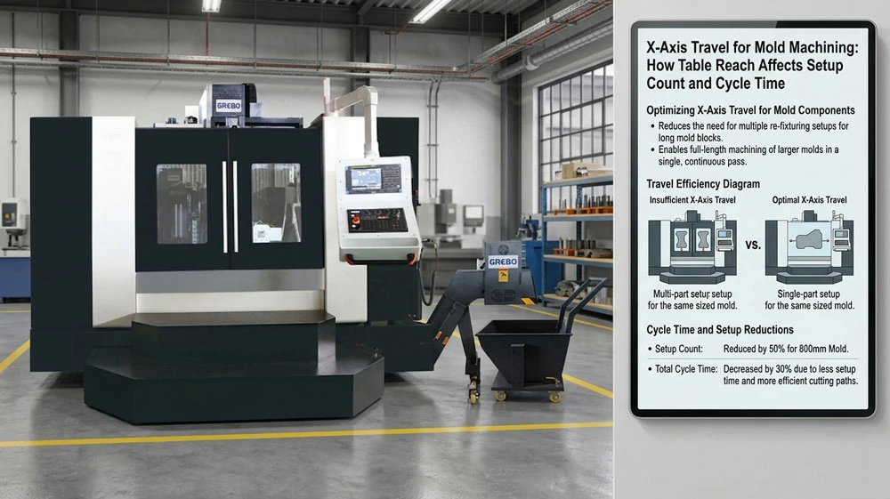
Put that same base on a 1300mm machine with a modular fixture. You machine the top and both long sides in the first clamping. One flip gets the bottom. Two setups. Handling time drops to 30 or 40 minutes. That 30 to 50 minutes you save per part goes straight back into your quoted cycle time.
This isn’t just theory. It’s simple geometry.
But why do shops still end up with the 800mm machine for a 1000mm part? Usually, it’s because of a classic sizing mistake. A buyer sees a 1000mm mold base and orders a machine with a 1000mm X-axis. Physically, the steel fits on the table. But there’s zero room for toe clamps, step blocks, or probe clearance. The operator ends up using sketchy minimal clamping that risks the part shifting during heavy roughing, or they just end up doing a second setup for the edges anyway. Rule of thumb: add 200 to 250mm to your max workpiece length to cover the hardware and safe tool clearance. If you don’t, your setup time will kill your quote.
Travel, Tool Reach, and Cavity Accessibility: The Engineering Link
X-axis travel does more than just decide if the part fits on the table. It dictates how far the spindle has to stretch to reach the work while keeping tool overhang ratios sane. When you’re hogging out deep cavities—say, 150mm to 300mm deep—a long tool overhang (anything past a 4:1 length-to-diameter ratio) is going to cause deflection and chatter, completely ruining your surface finish.
When your machining envelope is cramped, the programmer has to push the part right up against the table edge just so the spindle can reach the far side of the cavity. Now the spindle is stretched out, and you’re forced to baby the feeds and speeds. Give the table some extra travel, and you can center the part under the spindle. The tool reaches the cavity walls from a much more rigid position, and you can actually keep your cutting parameters aggressive.
| Parameter | 800mm Travel VMC | 1300mm Travel VMC |
|---|---|---|
| Max mold base length (single setup) | ~650mm | ~1100mm |
| Typical setups for 900mm mold base | 4 | 2 |
| Setup handling time per part | 60-90 min | 30-40 min |
| Tool overhang for far-side cavity | High (part near table edge) | Moderate (part centered) |
| Unattended runtime per setup | 2-3 hours | 4-6 hours |
| Fixture clearance margin | Tight (50-80mm) | Adequate (100-150mm) |
The table spells it out. A 1300mm machine isn’t just for bigger parts. It lets you machine the same parts with fewer operator interruptions, shorter tool extensions, and longer stretches of uninterrupted cutting. When it comes to setup reduction, that’s the difference between a machine making money and a machine waiting for a guy with an indicator.
Practical Scenarios: When 1300mm Travel Changes the Job
Let’s look at three real-world scenarios where table reach makes or breaks the job.
Scenario one: medium automotive mold bases. Take an 850x650mm bumper grill base. It needs all four faces machined, plus a bunch of drilled and tapped waterline holes around the perimeter. On an 800mm machine, hitting those perimeter holes on the long sides means unclamping and rotating the base 90 degrees. On a 1300mm machine, the whole perimeter gets done in one clamping. Your ±0.03mm positional tolerance on those waterlines holds up because you never broke the datum.
Scenario two: batch cavity inserts. You’ve got an order for twenty identical cavity inserts out of pre-hard steel, 120x80mm each. Instead of sticking them in a vise one by one, your programmer arrays six blanks across a 1000mm sub-plate. The 1300mm X-axis sweeps the whole array, leaving plenty of room for the clamps and the probe. The machine runs unattended for four hours, roughing and semi-finishing all six before the operator even walks back over. An 800mm machine maxes out at three blanks, doubling your load cycles.
Scenario three: large appliance housings. A washing machine drum base at 1050x750mm just flat-out won’t fit in a single setup on an 800mm machine. You’re left with two bad choices: farm the work out to a bigger shop down the street, or eat four setups and pray you don’t scrap it. A 1300mm machine handles it in two setups, keeping the job in-house and keeping your delivery promises.
For shops running a mixed bag of sizes, 1300mm is the sweet spot. It covers almost everything up to 1100mm without forcing you to buy a massive 2000mm gantry mill that takes up half your shop floor. It’s not for everyone, though. If you only ever run tiny inserts under 600mm, you’re just paying for cast iron you’ll never use. The ROI kicks in when your work mix actually demands the extra reach.
Other Common Mistakes When Specifying Travel for Mold Machining
Now, let’s talk about two other blind spots we see all the time when buyers spec out these machines.
Ignoring the Y-Axis and Z-Axis Relationship
X-axis gets all the glory because it’s the longest dimension. But mold bases are 3D. A machine with a massive 1300mm X-axis but a cramped 600mm Y and 500mm Z will still bottom out when you try to machine a deep cavity on a wide base. The envelope has to swallow the entire bounding box of the part, plus the tallest fixture and the longest tool stick-out. Looking at X-axis travel in a vacuum just gets you a machine that handles length but chokes on width and height.
Assuming Bigger Travel Always Means Better Efficiency
Look, extra travel means more cast iron, a bigger footprint, and higher power bills. If 95% of your work is 400mm inserts, you don’t need a 1300mm machine. That giant table is just going to spend all day rapiding across empty space, wearing out the linear guides for no reason. Buy the machine that matches your 95th percentile part size, not the one-off monster you quoted three years ago. Look at your actual job history before you sign the PO.
Decision Framework: How Much X-Axis Travel Do You Actually Need?
Every time a customer asks me if they should upgrade to a 1300mm machine, I make them fill out this scoring matrix first. Honestly, half the time they realize they’ve been focusing on the exact wrong thing. Rate each factor from 1 to 5, multiply by the weight, and tally it up.
| Evaluation Factor | Weight | Score (1-5) | Weighted Score |
|---|---|---|---|
| Percentage of mold bases over 700mm in longest dimension | 3.0 | ___ | ___ |
| Average setups per mold base on current equipment | 2.5 | ___ | ___ |
| Batch size of identical cavity inserts per run | 2.0 | ___ | ___ |
| Tolerance sensitivity to repositioning error (1=loose, 5=tight) | 2.5 | ___ | ___ |
| Floor space available for machine footprint expansion | 1.5 | ___ | ___ |
| Budget flexibility for larger machine class | 1.5 | ___ | ___ |
| Total Weighted Score | ___ | ||
Interpretation: If you score above 35, a 1300mm machine is going to pay for itself quickly through fewer setups and longer lights-out runs. Between 20 and 35, it’s a coin toss—dig into your specific job history before committing. Below 20, the extra travel is just dead weight. You’re better off buying a compact machine with lightning-fast rapids that’s optimized for the small inserts you actually run every day.
For those scoring above 35, a 1300mm VMC with a BT40 spindle and decent Z-axis stroke is the ultimate middle ground. It bridges the gap between small job-shop VMCs and massive dedicated mold mills. The BT40 vertical machining center series in this size range is built specifically for this kind of work, giving you the spindle torque and tool capacity you need for both single-setup bases and batch insert arrays.
Frequently Asked Questions
How much X-axis travel do I need for a 900mm mold base?
Take the 900mm part length and add 200 to 250mm for step blocks, clamps, tool approach, and probe clearance. So, you need 1100mm to 1150mm of usable travel for a true single-setup job. A 1300mm machine gives you a comfortable buffer and leaves room to throw a tombstone on the table for batch insert work later.
Does extra X-axis travel improve surface finish on mold cavities?
Indirectly, absolutely. Extra travel lets you mount the part in the dead center of the table instead of hanging it off the edge. That means your spindle isn’t stretched out. Less overhang means less chatter and deflection when you’re reaching into the far side of a deep cavity. You get a much cleaner surface finish on your semi-finish and finish passes. It makes a real difference.
Why not just use a smaller machine and accept more setups?
Look, you could just use a smaller machine. But every time you unclamp and re-zero a part, you eat up labor time and stack up tolerance errors. Each flip introduces a potential ±0.01mm to ±0.02mm datum shift. If you’re doing four setups on a base with tight waterline patterns, those errors compound fast and can easily push the part out of spec. Fewer setups save labor and keep the scrap bin empty. It’s really that simple.
Is 1300mm X-axis travel enough for all mold machining work?
No. If you’re machining bases for massive automotive dashboards or industrial pallets, they can easily exceed 1200mm and will require a 1500mm to 2000mm machine or a gantry mill. But for 80% of medium-sized mold bases and cavity insert work, 1300mm is more than enough. Shops heavily weighted toward oversized molds should look at gantry machining centers instead.
How does X-axis travel affect unattended production in mold shops?
Longer travel lets you gang up more parts on a single sub-plate. A 1300mm machine can comfortably hold a six-insert tombstone fixture and run unattended for four hours. An 800mm machine limits you to three inserts and maybe two hours of cutting before the operator has to swap them out. It’s the difference between a machine making chips while your guys are at lunch, and a machine sitting idle waiting for attention.
Related Reading
- For a broader view of how vertical and horizontal configurations affect mold work, see our analysis of vertical vs horizontal machining center selection.
- If your work includes complex cavity geometries that require angled tool access, explore how 5-axis machining centers reduce setup count for undercut features.
- For shops focused on high-volume insert production, our guide to tapping center vs machining center for small parts covers cycle time and batch throughput trade-offs.
Need help matching table travel to your mold base sizes? Our engineering team reviews part drawings and recommends the right machining envelope for your work mix.
Talk to us on WhatsApp or send your RFQ for a setup-time analysis based on your actual part geometry.