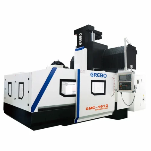

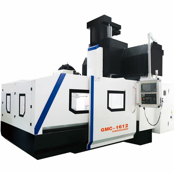

A gantry machining center with 1600 × 1000 mm table travel and a 15 kW BT50 belt-drive spindle handles mold-base roughing at a lower cost than large bridge mills. The fixed-column layout delivers maximum rigidity once workpiece width exceeds the limits of a moving-column VMC. Built in a CE-certified facility with 28,000 square meters of production space, this compact gantry machining center serves as an entry-level double-column solution for mold shops and fabrication facilities across 50-plus export markets.
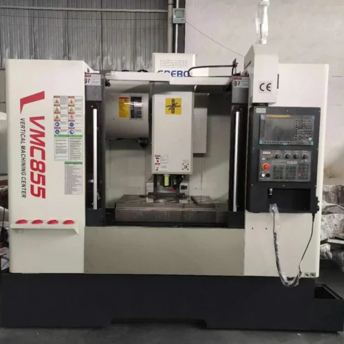
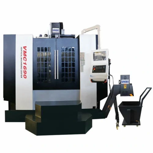
If your workpieces measure under 1.2 m and do not need the fixed-column rigidity of a gantry frame, a vertical machining center offers a more compact footprint and lower investment.
Key Features of This Gantry Machining Center
This entry-level gantry mill class pairs heavy-duty mechanical design with 0.005 mm repeat accuracy to support both roughing and semi-finishing in one setup.
If your mold bases stay under 1600 mm, the GMC1612 with a Φ50 mm ball screw and 2-ton table capacity keeps the investment minimal. For general 2000 mm mold work, the GMC2012 upgrades to a Φ63 mm screw and 8 guide blocks for heavier cuts. When you machine 2500 mm battery trays or long structural beams, the GMC2512 shifts to a 12 mm pitch on the X-axis to control screw whip over long travel, paired with 10 blocks and 4-ton capacity.
- The 15/18.5 kW BT50 belt-drive spindle delivers high torque at low rpm, allowing pre-hardened mold steels to cut cleanly without the chatter common in smaller taper setups.
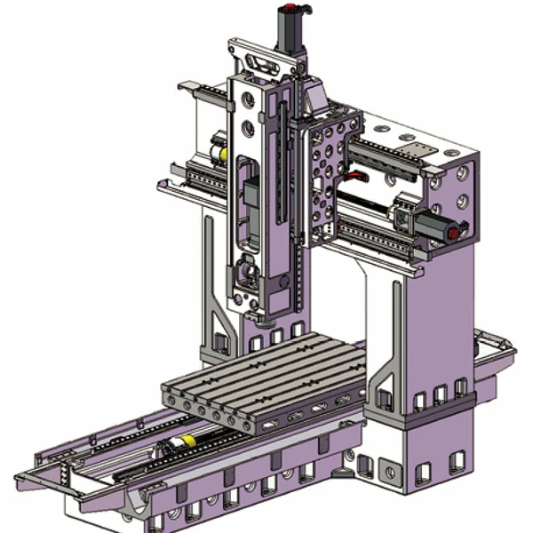
- A fixed dual-column frame with 1300 mm between columns supports the spindle head across the full table width, resisting deflection when cutter engagement spans wide mold cavities.
- The X-axis runs on Φ50–Φ63 mm ball screws with 6–10 guide blocks, increasing screw diameter and block count as travel grows from 1600 mm to 2500 mm to maintain positioning accuracy under load.
- Dual screw-type chip conveyors feed into a single chain conveyor, clearing heavy steel chips from both sides of the table before they accumulate under guideways during long roughing cycles.
- The nitrogen balance cylinder on the Z-axis ram counteracts head weight during vertical plunging and retract moves, reducing servo load and improving repeat positioning to 0.005 mm.
Note: The GMC2512 increases X-axis lead to 12 mm to compensate for longer screw whip at 2500 mm stroke. Do not specify 10 mm pitch on this model—it will not perform as rated.
Which GMC Model Fits Your Workpiece?
Select the right model based on your maximum workpiece dimensions and loading requirements to optimize your investment.
| Model | Best For | Max Loading Capacity |
|---|---|---|
| GMC1612 | Mold bases under 1600 mm | 2 Tons |
| GMC2012 | General mold and structural parts | 3 Tons |
| GMC2512 | Long plates and battery trays | 4 Tons |
Technical Specifications
The following table lists the specified parameters for the GMC1612, GMC2012, and GMC2512, including axis travel, spindle data, feed rates, and mechanical component specifications measured under ASME B5.54 evaluation protocols.
| Parameter | Unit | GMC1612 | GMC2012 | GMC2512 |
|---|---|---|---|---|
| X / Y / Z Axis Travel | mm | 1600 / 1300 / 800 | 2000 / 1300 / 800 | 2500 / 1300 / 800 |
| Spindle Nose to Worktable | mm | 115 – 915 | 115 – 915 | 115 – 915 |
| Distance Between Two Columns | mm | 1300 | 1300 | 1300 |
| Leadscrew Diameter (X/Y/Z) | mm | Φ50 / 50 / 50 (Pitch 10) | Φ63 / 50 / 50 (Pitch 10) | Φ63 / 50 / 50 (X Pitch 12) |
| Linear Guideway Width | mm | 45 / 45 / 45 | 45 / 45 / 45 | 45 / 45 / 45 |
| Block Qty (X/Y/Z) | pcs | 6 / 4 / 6 | 8 / 4 / 6 | 10 / 4 / 6 |
| Worktable Size | mm | 1600 × 1000 | 2000 × 1000 | 2500 × 1000 |
| T-Slot (No. × Width × Pitch) | mm | 7 × 22 × 140 | 7 × 22 × 140 | 7 × 22 × 140 |
| Max Loading Capacity | Ton | 2 | 3 | 4 |
| Spindle Taper | – | BT50 | BT50 | BT50 |
| Spindle Transmission | – | Belt Drive | Belt Drive | Belt Drive |
| Spindle Speed | rpm | 8000 | 8000 | 8000 |
| Spindle Motor Power | kW | 15 / 18.5 (Continuous / Peak) | 15 / 18.5 (Continuous / Peak) | 15 / 18.5 (Continuous / Peak) |
| X / Y / Z Fast Moving Speed | m/min | 15 / 15 / 15 | 15 / 15 / 15 | 15 / 15 / 15 |
| Cutting Speed | mm/min | 1 – 10000 | 1 – 10000 | 1 – 10000 |
| Tool Magazine Capacity and Type | pcs | 24 Disc Type | 24 Disc Type | 24 Disc Type |
| Positioning Accuracy | mm | 0.008 | 0.008 | 0.008 |
| Repeat Accuracy | mm | 0.005 | 0.005 | 0.005 |
| Machine Weight | kg | 14000 | 14800 | 15800 |
Standard Configuration
Every GMC1612, GMC2012, and GMC2512 ships with Mitsubishi M80A control, Taiwan-brand mechanical components, and a heavy-duty chip removal system as baseline equipment.
- Mitsubishi M80A CNC system
- X/Y/Z Mitsubishi servo motors and drives
- USB interface for program and data transfer
- Taiwan-brand BT50 belt-drive spindle unit, 8000 rpm
- Taiwan-brand 3-axis precision linear guideways
- Taiwan-brand precision ball lead screws
- Z-axis nitrogen balance cylinder
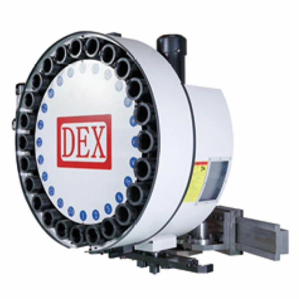
- 24-position disc-type tool magazine (DEX Taiwan)
- Screw-type chip conveyor × 2
- Chain-type chip conveyor and chip bucket × 1
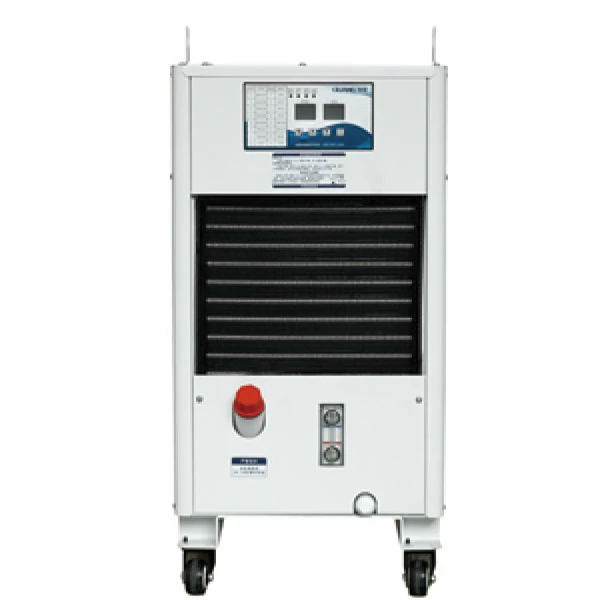
- Spindle oil cooler
- Centralized automatic lubrication system
- Electrical cabinet heat exchanger
- High-pressure air gun and coolant gun
- Levelling pads, nuts, and bolts
- Standard tools and tool box
Applications of This Gantry Machining Center
A compact gantry machining center in this size class covers electrode plate machining, cavity semi-finishing, and large flange facing on tables up to 2500 × 1000 mm.
- Electrode plate machining and cavity semi-finishing on pre-hardened mold inserts up to 40 HRC, where the BT50 spindle torque maintains stable chip loads without chatter across long open cuts.
- Large flange facing and boring on 2–4 ton weldments, using the 1300 mm Y stroke to machine oversized mounting surfaces in a single fixturing without repositioning the workpiece.
Typical Application Cases
These two scenarios illustrate how the GMC series performs in typical production environments where mold accuracy and weldment flatness drive purchasing decisions.
Typical Application: Small and Medium Plastic Mold Base Machining
Injection mold bases and electrode plates in the 1600 × 1000 mm range demand square face milling and precise guide-hole drilling in one setup. Moving-table designs introduce column deflection over long open cuts.
- The GMC1612/2012 fixed gantry maintains perpendicularity across the full table width while the BT50 15 kW spindle roughs cavities and finishes guide bores without secondary fixturing.
- Bringing mold-base machining in-house can help manufacturers reduce outsourcing dependency and improve production control.
Typical Application: Post-Weld Precision Machining on Machine Base Plates
Welded structural frames and machine base plates up to 4 tons retain internal stress and heat distortion after fabrication. The GMC2512 supports these loads across its 2500 × 1000 mm table while dual screw-type chip conveyors clear heavy irregular chips before they jam guideways.
- The 1300 mm Y-axis stroke covers wide plates in a single pass, restoring flatness and bore alignment.
- Surface flatness typically holds within 0.05 mm/m, and repeat positioning at 0.005 mm restores assembly datum surfaces without manual scraping.
Industries Served
Mold manufacturing shops and general fabrication facilities use this gantry machining center class for everything from P20 cavity roughing to structural frame milling. The 1300 mm column span and BT50 spindle bridge the gap between vertical machining centers and oversized bridge mills. For mold work exceeding 2.5 m or requiring greater column span, our CNC gantry milling machine line steps up to the next size class.
Frequently Asked Questions
The answers below cover when to choose a gantry over a VMC, how the fixed-column frame maintains rigidity, foundation requirements, and roughing-versus-finishing capability.
When is a gantry machining center preferable to a moving-column VMC?
A gantry machining center becomes the better choice once workpiece width exceeds the point where a moving-column VMC starts to cantilever. The fixed dual-column frame supports the spindle across the full table width without deflection, so wide mold bases and heavy weldments machine more accurately on gantry tables. Parts under 1.2 m still suit a VMC better.
How does the gantry structure maintain rigidity across a wide worktable?
The 1300 mm fixed column span, paired with 45 mm linear guideways and 6–10 guide blocks on the X-axis, distributes cutting forces directly into the bed rather than through a single moving column. That load path resists spindle deflection when cutter engagement spans wide cavities or heavy roughing passes.
What foundation requirements apply to large gantry machining centers?
At 14–16 tons, these machines need an independent concrete foundation isolated from stamping or forging vibration. Floor levelness should hold within 0.05 mm/m, and anchor bolt spacing must match the levelling pad pattern supplied with the machine to prevent bed twist over long travel distances.
Can gantry machining centers handle both roughing and precision finishing?
The BT50 15 kW belt-drive spindle delivers high torque for pre-hardened steel roughing, while the 8000 rpm top speed and 0.005 mm repeat accuracy support semi-finishing and bore reaming in the same setup. Though dedicated high-speed bridge mills exceed this spindle speed, the GMC series covers the rough-to-finish range typical of mold and structural part workflows.