
Extra Large Gantry Machining Center Built for Long-Span Heavy Cutting
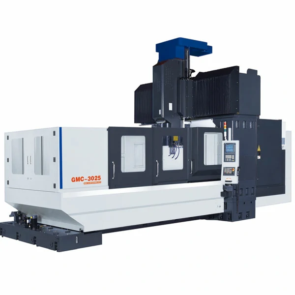
The GMC3025 through GMC6025 lineup keeps the Y-axis travel and working envelope consistent at 2700mm and 2300mm respectively, while scaling the X-axis structure according to stroke length. This wider 2700mm column spacing (compared to standard 2000-2300mm gantries) provides additional working clearance and contributes to structural rigidity for massive 10-18 ton workpieces. Manufactured by a Shandong-based facility operating since 2005 under ISO 9001:2008 and CE certification, this series targets oversized mold bases, heavy machinery frames, and large structural parts that outgrow conventional large CNC gantry mills.
Key Features
This lineup functions as a gantry machining center for heavy duty cutting because each model’s structural upgrade tracks its stroke length rather than a generic specification increase.
- The X-axis ballscrew steps from Φ80mm on the GMC3025-GMC5025 to Φ100mm on the GMC6025, providing the structural mass required for full 6000mm travel.
- X-axis guide block count rises from 10 pieces on the GMC3025 to 18 on the GMC6025, distributing cutting loads and improving resistance against overturning moment and vibration during heavy cuts.
- A box-way Z-axis paired with 55mm linear guides on X and Y forms the primary load path for heavy cuts, while the nitrogen balance cylinder steadies the spindle head through feed changes.
- Worktable loading capacity reaches 18 tons on the GMC6025, accommodating oversized mold bases and structural castings that exceed the limits of smaller gantry classes.
Engineering Insights: Matching Ballscrew and Guide-Block Configuration to Travel Length
Model selection in this series follows one rule: match ballscrew diameter and guide-block count to actual travel length rather than defaulting to the largest available model.
If a workpiece stays under 3000mm and does not need this series’ extended X-axis travel, a standard gantry machining center covers that range at a lower structural cost.
Across the GMC3025 through GMC5025, a Φ80mm/20mm-pitch ballscrew with 10-14 guide blocks is configured for 3000-5000mm of travel. At the full 6000mm stroke, the GMC6025 steps up to a Φ100mm screw and 18 guide blocks spread along the beam to manage the extended overhang. Workpieces beyond 6000mm move into the Ultra Large Double Column Machining Center range instead.
Engineer’s note: do not spec the GMC6025 for extra length alone. If the workpiece stays under 5m, the GMC5025’s smaller ballscrew and block count already deliver comparable rigidity at a lower cost.
Technical Specifications
The table below lists axis travel, structural, and drive specifications across all four Extra Large Gantry Machining Center models in this series.
| Parameter | Unit | GMC3025 | GMC4025 | GMC5025 | GMC6025 |
|---|---|---|---|---|---|
| X / Y / Z Axis Travel | mm | 3000 / 2700 / 1000 | 4000 / 2700 / 1000 | 5000 / 2700 / 1000 | 6000 / 2700 / 1000 |
| Spindle Nose to Worktable | mm | 280 – 1280 | 280 – 1280 | 280 – 1280 | 280 – 1280 |
| Distance Between Columns | mm | 2700 | 2700 | 2700 | 2700 |
| Ballscrew Diameter/Pitch (X/Y/Z) | mm | X: Φ80/20, Y: Φ63/16, Z: Φ50/10 | X: Φ80/20, Y: Φ63/12, Z: Φ50/10 | X: Φ80/20, Y: Φ63/12, Z: Φ50/10 | X: Φ100/20, Y: Φ63/12, Z: Φ50/10 |
| Guideway Type/Width (X/Y/Z) | mm | X/Y: 55 linear, Z: Box way | X/Y: 55 linear, Z: Box way | X/Y: 55 linear, Z: Box way | X/Y: 55 linear, Z: Box way |
| X/Y Axis Guide Block Qty | pcs | 10 / 4 | 14 / 4 | 14 / 4 | 18 / 4 |
| Worktable Size | mm | 3000 x 2300 | 4000 x 2300 | 5000 x 2300 | 6000 x 2300 |
| T-slot (Qty x Width x Pitch) | mm | 11 x 28 x 200 | 11 x 28 x 200 | 11 x 28 x 200 | 11 x 28 x 200 |
| Max Loading Capacity | Ton | 10 | 12 | 15 | 18 |
| Spindle Taper | – | BT50 | BT50 | BT50 | BT50 |
| Spindle Transmission | – | Belt drive | Belt drive | Belt drive | Belt drive |
| Spindle Speed | rpm | 6000 | 6000 | 6000 | 6000 |
| Spindle Motor Power | kW | 22 | 22 | 22 | 22 |
| X/Y/Z Fast Moving Speed | m/min | 10 / 10 / 10 | 10 / 10 / 10 | 10 / 10 / 10 | 10 / 10 / 10 |
| Cutting Feed Speed | mm/min | 1 – 6000 | 1 – 6000 | 1 – 6000 | 1 – 6000 |
| Tool Magazine Capacity & Type | pcs | 24, Disc type | 24, Disc type | 24, Disc type | 24, Disc type |
| Positioning Accuracy | mm | 0.008 | 0.008 | 0.008 | 0.008 |
| Repeat Accuracy | mm | 0.005 | 0.005 | 0.005 | 0.005 |
| Machine Net Weight | kg | 33000 | 38000 | 43000 | 50000 |
Positioning and repeat accuracy figures are measured according to standard machine tool acceptance testing procedures.
Standard Configuration
The following components ship as standard equipment across all four GMC3025-GMC6025 models in this series.
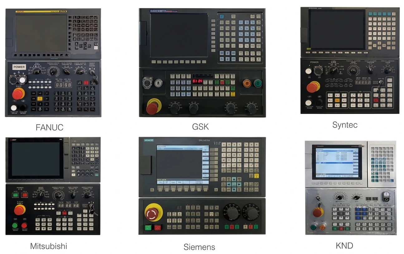
- Mitsubishi M80A CNC controller with Mitsubishi servo motors and drivers on X/Y/Z axes
- Taiwan-brand spindle unit (Kenturn or Royal), belt drive, 6000 rpm maximum speed
- Taiwan-brand 55mm precision linear guides on X/Y axes; box way on Z-axis
- Taiwan-brand precision ballscrews
- Nitrogen balance cylinder on the Z-axis spindle head
- 24-tool disc-type tool magazine
- Screw-type chip conveyor x 2
- Chain-type chip conveyor and chip bucket x 1
- Automatic centralized lubrication system
- Heat exchanger for the electrical cabinet
- Air gun and water gun
- Leveling pads, nuts and bolts
- Standard tools and tool box
Typical Application Cases
Typical applications for this series involve workpieces requiring extended travel and high load capacity.
Typical Application: Automotive Stamping Mold Base Machining
Large stamping mold bases and injection mold templates near 5000 x 2000mm and 15 tons typically need a single-setup finish to avoid a stepped mismatch at the parting line. On a GMC5025 or GMC6025, the 2700mm Y-axis travel and 2300mm worktable hold the full base in one fixture. The machine provides 0.008mm positioning accuracy according to standard test methods, while its heavy structure supports the 15-18 ton load.
- Single-setup machining across a 5000x2000mm base
- Positioning accuracy held at 0.008mm across full travel
- Worktable load rated to 15-18 tons
Typical Application: Aerospace Structural Frame Milling
Aircraft structural frames and spar sections 4-6m long typically require tight form-tolerance control, which a standard ballscrew can lose near the stroke end under sustained cutting loads. The GMC6025’s Φ100mm ballscrew and 18-block distributed support manage the extended 6000mm travel, while the box-way Z-axis and BT50 spindle handle heavy aerospace aluminum and structural alloy removal.
- Sustains positioning accuracy across a 4-6m structural part
- Box-way Z-axis holds stability under sustained material removal
- BT50 spindle taper supports rigid heavy-cut tool engagement
Typical Application: Wind Power and Heavy Machinery Base Cutting
Wind turbine bases and heavy machinery frames in the 12-18 ton range typically carry uneven stock and heavy chip loads that pack against the guideways on a 2300mm-wide table. The GMC4025 through GMC6025 support up to 18 tons of table loading, and the combined chip conveyor system is sized to clear that volume from both sides of the 55mm linear guides during continuous cutting.
- Worktable capacity up to 18 tons for heavy castings
- Combined chip conveyor system clears a 2300mm-wide table
- 22kW spindle sustains continuous roughing passes
Frequently Asked Questions
The following questions address the most common sizing and structural considerations for this series.
What are the advantages of fixed-gantry design for large mold bases?
A fixed-gantry design keeps the worktable stationary while the beam and spindle head move, so a large mold base stays clamped in one position throughout roughing and finishing. This reduces repositioning requirements compared with layouts that require moving or re-fixturing large workpieces.
What is the maximum workpiece size this gantry machining center can accommodate?
Across the GMC3025 to GMC6025 range, worktable size scales from 3000x2300mm to 6000x2300mm, with Y-axis travel fixed at 2700mm on all four models. Workpiece length should stay within the chosen model’s X-axis travel, and width should stay under the 2300mm table dimension.
How does the gantry structure handle cutting deflection toward the table ends?
Deflection resistance comes from ballscrew diameter and guide-block distribution along the beam. On this series, the GMC6025 uses a Φ100mm ballscrew and 18 guide blocks instead of the Φ80mm/10-14 block setup on smaller models, which controls beam vibration as the spindle head approaches full 6000mm extension.
What foundation requirements apply to large gantry machining centers?
Machine net weight in this series ranges from 33,000kg to 50,000kg, so foundation design should account for point loading under the columns and worktable rather than an even floor load. A level, reinforced concrete base sized to the specific model’s footprint and weight is standard practice before installation.
Need help selecting between GMC3025, GMC4025, GMC5025, and GMC6025 for your workpiece size and cutting load?