
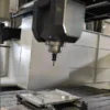
Large Gantry Machining Center for Heavy Structural Parts
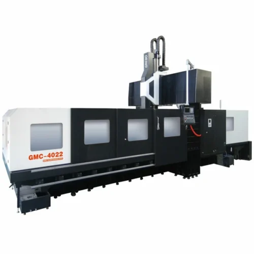
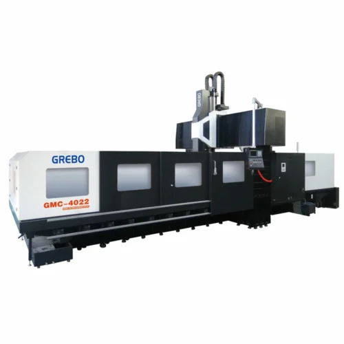
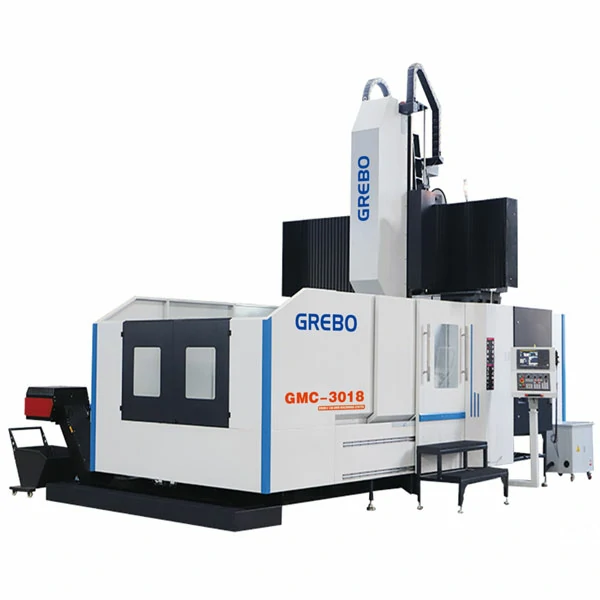
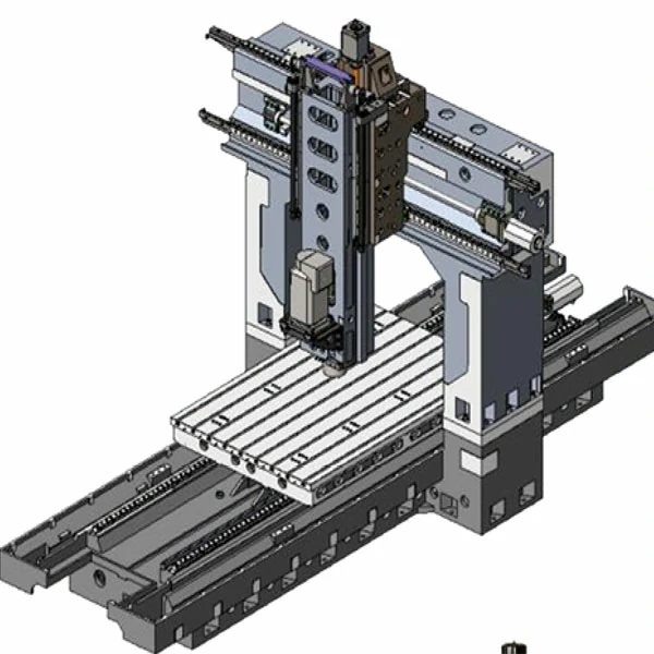
This large gantry machining center handles 7.5-ton worktable loads and 3500mm X-axis travel, managing structural parts that overload standard moving-column layouts. It pairs a BT50 belt-drive spindle with a fixed dual-column frame to keep the spindle head rigid across the full 1900mm Y-axis span. If your parts fit within a 1600mm width and do not need this mass capacity, a compact gantry machining center will serve you better.
Key Features and Structural Design
Machines in this size class rely on guideway span and ballscrew diameter to maintain accuracy across wide worktables.
- X and Y axes use 55mm-wide linear guideways with six to ten blocks per axis. This distributes cutting loads across a broad contact surface, maintaining positioning accuracy during heavy roughing.
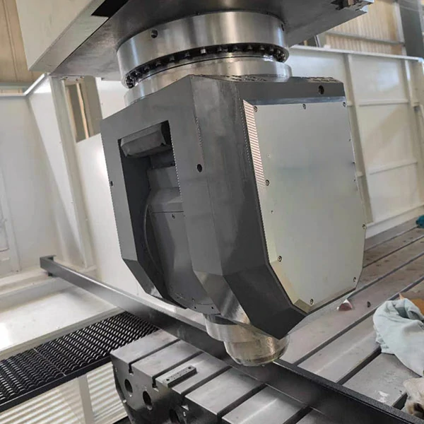
- A box-way Z axis and nitrogen balance cylinder support the 800mm vertical stroke. The spindle head resists deflection even when the tool extends 1000mm below the nose for deep-cavity milling.
- The BT50 belt-drive spindle outputs 18.5kW continuous and 22kW peak power at 6000rpm. It delivers the low-speed torque needed for cast-iron roughing without the gear noise of a direct-drive head.
- Dual screw-type chip conveyors and one chain-type unit clear swarf from the 1600mm-wide table. This keeps the 55mm guideways free of abrasive chip piles that accelerate wear.
Why Choose a Fixed-Gantry Structure for Large Structural Parts?
Large and heavy workpieces can place significant loads on the machine structure. A fixed gantry keeps the columns and crossbeam stationary while the table and workpiece move along the X-axis. This design provides a highly rigid and stable machining envelope for large components, avoiding the overhang and spindle deflection inherent in moving-column designs.
Engineering Insights: X-Axis Ballscrew Selection
As X-axis travel increases, ballscrew diameter, pitch, and support configuration become increasingly important for maintaining axial stiffness and controlling deformation during heavy cutting.
The GMC2018 uses a Φ50mm / 10mm-pitch X-axis ballscrew for its 2000mm travel. The GMC2518 and GMC3018 use a Φ63mm / 12mm-pitch screw to provide additional stiffness across their 2500mm and 3000mm strokes.
For the 3500mm X-axis travel of the GMC3518, a Φ80mm / 16mm-pitch ballscrew is used as part of the long-travel axis design. The larger screw diameter provides greater resistance to bending and torsional deformation under heavy machining loads, helping to maintain 0.008mm positioning and 0.005mm repeat accuracy.
Large Gantry Machining Center Technical Specifications
The GMC2018–GMC3518 series offers X-axis travel from 2000mm to 3500mm with graded mechanical components.
| Parameter | Unit | GMC2018 | GMC2518 | GMC3018 | GMC3518 |
|---|---|---|---|---|---|
| X / Y / Z Axis travel | mm | 2000 / 1900 / 800 | 2500 / 1900 / 800 | 3000 / 1900 / 800 | 3500 / 1900 / 800 |
| Spindle nose to worktable | mm | 200 – 1000 | 200 – 1000 | 200 – 1000 | 200 – 1000 |
| Distance between two columns | mm | 1900 | 1900 | 1900 | 1900 |
| Leadscrew dia./pitch (X/Y/Z) | mm | Φ50 / 10 (all axes) | X: Φ63 / 12; Y/Z: Φ50 / 10 | X: Φ63 / 12; Y/Z: Φ50 / 10 | X: Φ80 / 16; Y/Z: Φ50 / 10 |
| Guideway type/width (X/Y/Z) | mm | X/Y: 55 linear; Z: Box way | X/Y: 55 linear; Z: Box way | X/Y: 55 linear; Z: Box way | X/Y: 55 linear; Z: Box way |
| Block Qty (X / Y) | pcs | 6 / 4 | 8 / 4 | 10 / 4 | 10 / 4 |
| Worktable size | mm | 2200 x 1600 | 2700 x 1600 | 3200 x 1600 | 3700 x 1600 |
| T-slot (Qty x Width x Pitch) | mm | 9 x 22 x 180 | 9 x 22 x 180 | 9 x 22 x 180 | 9 x 22 x 180 |
| Max loading capacity | Ton | 4.5 | 5.5 | 6.5 | 7.5 |
| Spindle taper | – | BT50 | BT50 | BT50 | BT50 |
| Spindle transmission | – | Belt drive | Belt drive | Belt drive | Belt drive |
| Spindle speed | rpm | 6000 | 6000 | 6000 | 6000 |
| Spindle motor power | kW | 18.5 / 22 | 18.5 / 22 | 18.5 / 22 | 18.5 / 22 |
| Fast moving speed (X/Y/Z) | m/min | 15 / 15 / 15 | 15 / 15 / 15 | 15 / 15 / 15 | 15 / 15 / 15 |
| Cutting feed rate | mm/min | 1 – 10000 | 1 – 10000 | 1 – 10000 | 1 – 10000 |
| Tool magazine capacity and type | pcs | 24 Disc | 24 Disc | 24 Disc | 24 Disc |
| Positioning accuracy | mm | 0.008 | 0.008 | 0.008 | 0.008 |
| Repeat accuracy | mm | 0.005 | 0.005 | 0.005 | 0.005 |
| Weight | kg | 18000 | 20000 | 21500 | 23000 |
Positioning and repeat accuracy values reference ISO 230-2:2014 test methods.
How to Choose the Right GMC Model
| Model | X Travel | Table Load | Typical Workpiece |
|---|---|---|---|
| GMC2018 | 2000 mm | 4.5 t | 2 m-class structural parts |
| GMC2518 | 2500 mm | 5.5 t | Medium-large weldments |
| GMC3018 | 3000 mm | 6.5 t | Heavy structural components |
| GMC3518 | 3500 mm | 7.5 t | Large and heavy structural parts |
Not sure which model fits your workpiece? Send us the workpiece dimensions, weight, material, and machining requirements. We can recommend the suitable machine configuration.
Standard Configuration
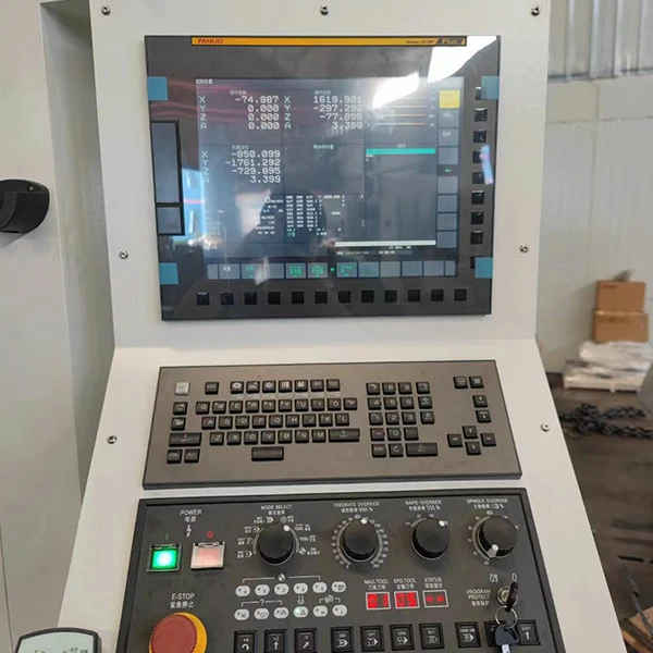
Every model includes a Mitsubishi M80A controller, BT50 belt-drive spindle, and dual chip-conveyor layout as standard.
CNC and Drive System
- Mitsubishi M80A controller
- Mitsubishi servo motors and drives on X/Y/Z axes
Spindle and Mechanical Transmission
- Belt-drive spindle unit, max 6000rpm
- X/Y axes: Taiwan-brand 55mm-wide precision linear guideways
- Z axis: Box way for heavy cutting rigidity
- Taiwan-brand precision ball leadscrew
- Nitrogen balance cylinder on Z axis (spindle head)
Tool Magazine and Chip Removal (Heavy-Duty Layout)
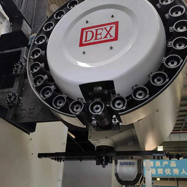
- 24 tools disc type ATC
- Screw type chip conveyor x 2
- Chain type chip conveyor and chip bucket x 1
Cooling, Lubrication and Protection
- Automatic lubricating system
- Heat exchanger for electrical cabinet
Standard Accessories
- Air gun and water gun
- Leveling pad, nut and bolts
- Tools and tool box
Typical Application Cases
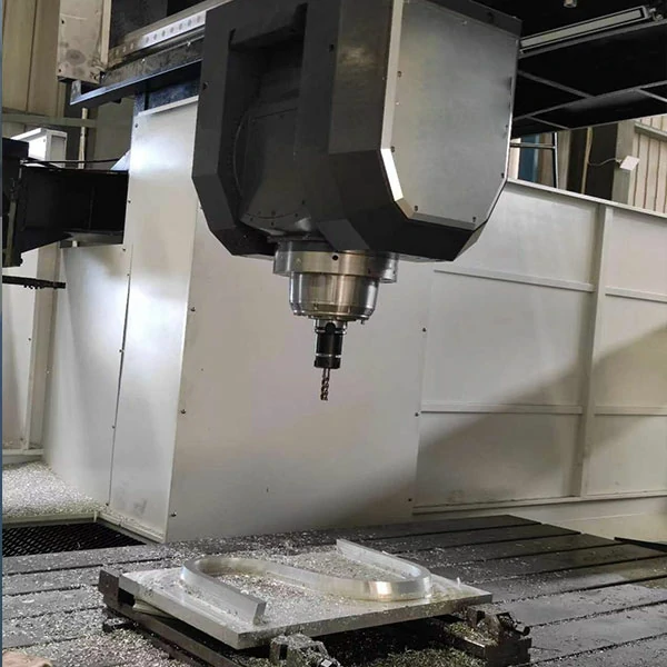
Applications for this large gantry machining center include heavy weldments and cast-iron housings that demand both rigidity and precision.
Typical Application: Excavator Base Weldment Finishing
- Workpiece: Excavator swivel base / loader frame
- Material: Welded structural steel
- Machine: GMC2518 or GMC3018
- Machining operations: Face milling, reference surface machining, hinge bore machining
- Result: The rigid gantry structure helps maintain cutting stability and geometric accuracy when machining large welded structures. Base mounting-face flatness is typically held to 0.05mm/m, and hinge-bore coaxiality stays within 0.02mm under standard test conditions.
Typical Application: Wind-Turbine Gearbox Housing Heavy Cutting
- Workpiece: Wind-turbine gearbox housing
- Material: HT250 or HT300 cast iron
- Machine: GMC3018 or GMC3518
- Machining operations: Heavy roughing, precision finishing of bearing seats
- Result: The rigid gantry structure and box-way Z axis help reduce vibration during heavy cast-iron roughing, particularly when cutting conditions generate high radial and axial loads. Bearing-bore surface finish reaches Ra 1.6μm, and bore position tolerance stays within ±0.015mm in internal trial machining.
Internal test result under specified machining conditions. Actual results vary with tooling, material, workholding, and cutting parameters.
Frequently Asked Questions
Buying a large gantry machining center for structural parts raises questions about foundation loads, workpiece limits, and deflection control. These differ from smaller machine tools.
When is a gantry machining center preferable to a moving-column VMC?
Choose a gantry layout when the workpiece width exceeds the limit where a moving-column design starts to cantilever. The fixed dual-column frame supports wide tables without spindle deflection toward the ends. This suits heavy structural parts over 1600mm wide and rated for loads above four tons.
What is the maximum workpiece size this gantry machining center can accommodate?
The GMC3518 provides 3500 × 1900 × 800mm X/Y/Z travel. Actual workpiece dimensions depend on workholding, fixture height, tool length, and required machining clearance. The GMC2018 provides 2000mm X-axis travel. Select the model that matches your largest regular workpiece requirements.
What foundation requirements apply to large gantry machining center installations?
Foundation requirements should be determined according to the machine model, site conditions, and the manufacturer’s foundation drawing. Because the GMC series weighs approximately 18,000kg to 23,000kg, adequate floor load capacity and foundation stability are essential for maintaining machine accuracy.
How does the gantry structure handle cutting deflection toward the table ends?
X-axis guideways use six to ten blocks per rail to spread cutting forces. The fixed gantry frame avoids the overhang inherent in moving-column designs. The box-way Z axis adds damping mass, keeping deflection consistent across the full 3500mm stroke.
Get a detailed proposal for your structural parts workflow.