
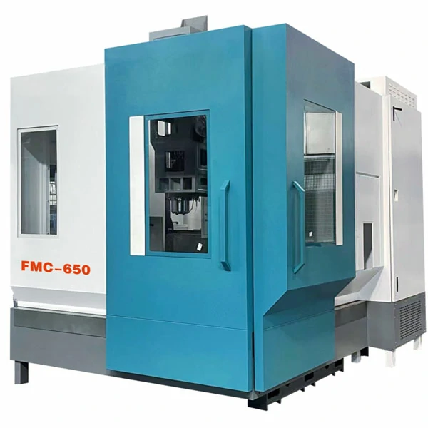
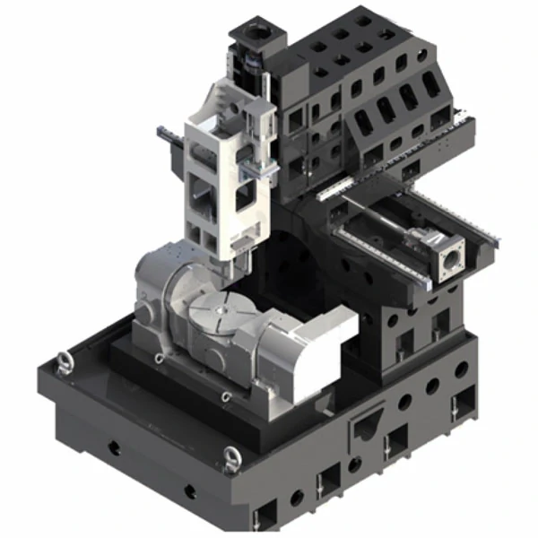
Each version pairs a Siemens 840D SL controller with a direct-drive rotary table. This keeps the RTCP path consistent whether machining a small medical fixture or a heavier aerospace bracket, while spindle taper, guideway type, and load capacity scale across the range.
These three models suit buyers who need a single setup for complex-geometry parts. They transition smoothly between small precision work and larger structural or mold components without changing platforms. All models are produced under ISO 9001:2008 and CE-certified quality systems, maintained since the manufacturer began building CNC machine tools in 2005.
Key Features
The FMC series maintains five-axis positioning accuracy through a combination of drive design and thermal control, rather than relying on a single headline specification.
- The direct-drive rotary table reduces transmission error compared with traditional geared rotary systems, improving accuracy during simultaneous 5-axis contouring and helping achieve consistent surface finishes on curved aerospace and medical surfaces.
- A spindle oil cooler controls thermal growth on the 12,000-20,000 rpm electric spindles, helping maintain surface finish consistency during long, unattended finishing cycles on complex parts.
- Direct-coupled servo motors on the X/Y/Z and rotary axes minimize transmission backlash. This supports positioning repeatability, whether the part sits on the FMC170’s ball-type linear guideways or the FMC650’s roller-type linear guideways.
- The FMC650 features 45mm roller linear guideways and a 300kg load rating. This supports cutting rigidity under heavy loads, accommodating workpieces that the FMC170’s lighter ball-guideway configuration is not designed to carry.
Optional Configurations
Controller choice determines the machine’s production capabilities. The standard Siemens 840D SL handles demanding simultaneous toolpaths. Alternatively, the FANUC 0i-MF, Siemens 828D, Mitsubishi M80A/B, or Syntec 22MA-5 serve as cost-effective options where budget or existing CAM workflows take priority over peak RTCP performance.
A 32-position chain-type magazine suits parts requiring frequent tool changes across multiple operations. The 30-bar through-spindle coolant (TSC) option clears chips and controls heat during deep-pocket cutting. Adding a 3-axis linear scale system with full closed-loop control provides direct position feedback for tight-tolerance runs.
For five-axis work, a Renishaw OMP60 touch probe and TS-27R tool setter are highly recommended. RTCP accuracy depends on knowing the exact center of rotation, which in-machine probing verifies without removing the part from the table.
Engineering Insights
Model Selection Note: The FMC170 (BT30 spindle, 8-tool magazine, 50kg capacity) is optimized for small, high-speed precision parts. For medium to large structural or mold components requiring BT40 tooling, 24-tool capacity, and 200-300kg load ratings, the FMC320 or FMC650 is required.
Shops moving into complex 3D contour work for aerospace or medical parts need a machine that holds rotary-axis accuracy through the full B/C rotation range. This requirement favors a direct-drive table over a worm-gear design. The FMC series pairs this table with the 840D SL’s RTCP algorithm and a spindle oil cooler. This maintains correct tool orientation as the spindle heats up during long finishing cycles, with repeat accuracy tested according to ISO 230-2:2014 methods.
Engineer’s note: verify FMC170 spindle and tool magazine specifications in writing before ordering. The smaller model runs a 20,000 rpm BT30 spindle and an 8-tool magazine, which differ from the FMC320/650’s 12,000-15,000 rpm BT40 configuration.
A five-axis trunnion table adds cost without adding usable capability for large structural weldments or bridge-type frames. For that class of workpiece, a gantry machining center is a more cost-effective route.
For aerospace or energy structural parts exceeding the FMC650’s Φ650mm envelope, the heavier Heavy Duty Gantry Machining Center platform takes over.
5-Axis Machining Center Technical Specifications
The table below lists travel, spindle, tooling, and drive specifications for the FMC170, FMC320, and FMC650 trunnion-table models.
| Parameter | Unit | FMC170 | FMC320 | FMC650 |
|---|---|---|---|---|
| Table Size (Diameter) | mm | Φ200 | Φ400 | Φ650 |
| X/Y/Z Axis Travel | mm | 600/200/300 | 800/360/400 | 820/520/500 |
| B-Axis/C-Axis Travel | deg | ±110° / 360° | ±110° / 360° | ±110° / 360° |
| Spindle Nose to Table Distance | mm | 80-380 | 150-550 | 150-650 |
| Spindle Center to Column Distance | mm | 140 | 183.5 | 187 |
| 5-Axis Rotary Table Model | – | TB-YL-200 | TB-YL-400 | TB-YL-650 |
| T-Slots (Qty x Width x Pitch) | mm | 4 x 12 x 90 | 8 x 14 x 45 | Customized according to rotary table configuration |
| Spindle Taper | – | BT30 | BT40-120 | BBT40-150 (Big Plus BT40) |
| Max. Spindle Speed | rpm | 20,000 | 12,000 | 15,000 |
| Tool Magazine Capacity & Type | pcs | BT30 / 8T | BT40 / 24T (disc type) | BT40 / 24T (disc type) |
| X/Y/Z Linear Guideway Size & Type | mm | 30mm ball-type | 35mm roller-type | 45mm roller-type |
| X/Y/Z Ball Screw Diameter/Pitch | mm | 3210/3210/3210 | 4012/4012/3212 | 4012/4012/4012 |
| Max. Loading Capacity | kg | 50 | Horizontal 200 / Tilted 160 | 300 |
| X/Y/Z Motor Connection | – | Direct-coupled | Direct-coupled | Direct-coupled |
| Main Spindle Motor Power | kW | 3.7/5.5 (continuous/peak) | 7.5 | 11 |
| X/Y/Z Rapid Traverse | m/min | 30/30/30 | 36/36/36 | 24/24/24 |
| Feed Motor Torque (X/Y/Z) | Nm | 16/12/16 | 22/22/22 | 22/22/22 |
| X/Y/Z Positioning Accuracy | mm | 0.008 | 0.008 | 0.008 |
| X/Y/Z Repeat Accuracy | mm | 0.005 | 0.005 | 0.005 |
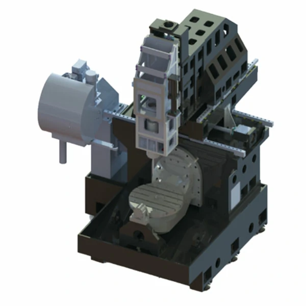
Standard Configuration
Standard configuration on every FMC model centers on a Siemens 840D SL control platform paired with direct-drive axis and rotary drives.
Control & Drive System
- Siemens 840D SL CNC controller
- X/Y/Z axis and rotary table servo drive motors with direct-coupled transmission
Spindle & Mechanical Drive
- FMC170: 20,000 rpm electric spindle, BT30 taper
- FMC320/FMC650: 12,000-15,000 rpm electric spindle, BT40/BBT40 taper
- Spindle oil cooler
- Taiwan-brand precision linear guideways (ball type on FMC170, high-rigidity roller type on FMC320/650)
- Taiwan-brand precision ball screws
- Taiwan-brand direct-drive 5-axis rotary table
Tool Magazine & Chip Removal
- FMC170: 8-position tool magazine (BT30)
- FMC320/FMC650: 24-position disc-type tool magazine (BT40)
- Chain and screw-type chip conveyor combination
Cooling, Protection & Auxiliary
- Electrical cabinet air conditioner
- Fully enclosed protective cover
- Centralized automatic lubrication system
- High-pressure air gun + coolant water gun
- Work light & three-color warning light
- Manual pulse generator (MPG)
Typical Application Cases
The scenarios below describe typical FMC-series applications derived from the platform’s rated spindle, rotary-table, and guideway specifications, rather than named customer projects.
Aerospace Compressor Impellers and Turbine Blades
Compressor impellers and turbocharger blades feature complex 3D contours with tight surface finish requirements. Using 3+2 positioning on titanium or aluminum alloys often requires multiple repositioning steps, which can accumulate errors and risk tool interference on tight blade clearances.
Operating as a 5-Axis CNC Machine for Aerospace Parts, the FMC320 or FMC650 uses a direct-drive table and the 840D SL’s RTCP algorithm. This maintains correct tool orientation to the blade surface through continuous simultaneous motion, while the spindle oil cooler limits thermal drift that would otherwise shift accuracy over a multi-hour cycle.
- Fewer repositioning steps per blade set due to continuous 5-axis contouring versus 3+2 processing
- Improved form control across adjoining blade surfaces through RTCP-guided tool orientation
- Reduced risk of tool-to-part interference on undercut blade geometry
Precision Medical Implants and Small Surgical Fixtures
Implant components, such as joint replacement parts and small surgical fixtures, require a contact-surface finish that limits wear and reduces rejection risk. These parts are often small enough that standard cutting forces can deflect or burr thin-wall titanium features.
The FMC170’s Φ200mm table and 20,000 rpm BT30 spindle are sized for this class of part. Running at high speed with lighter chip loads maintains low cutting forces, helping avoid deflection on thin sections. As a 5-Axis Machining Center for Complex Parts Machining, the FMC170 completes compound-angle and eccentric-hole features in a single setup.
- Lower cutting force at high spindle speeds, reducing deflection risk on thin-wall titanium sections
- Compound-angle and eccentric-hole features completed without a second fixture setup
- Fewer repositioning steps compared to 3-axis processing for the same feature set
FAQ
Common specification and selection questions about the FMC series are answered below.
What is the difference between 3+2 positioning and full simultaneous 5-axis machining?
3+2 positioning locks the rotary axes at a fixed angle for each operation, then cuts in three linear axes. This works for angled faces but still requires repositioning between features. Full simultaneous 5-axis machining moves all five axes together during the cut, allowing a 5-axis machining center to follow continuously curved surfaces in a single pass.
How does a trunnion table affect access to complex geometries?
A trunnion-style rotary table tilts the workpiece on the B-axis while the C-axis rotates it. This brings undercuts, compound angles, and deep pockets into the tool’s reach without repositioning the part, allowing one setup to complete features that would otherwise require multiple fixture changes on a 3-axis machine.
What tooling and CAM considerations apply to 5-axis programming?
Simultaneous 5-axis toolpaths require CAM software with collision checking against the rotary table and fixture, along with tool holders short enough to avoid interference at extreme B-axis angles. Cutting parameters also require adjustment per axis orientation, as chip load and effective cutting speed change when the tool tilts relative to the surface.
What industries most commonly require 5-axis machining centers?
Aerospace component manufacturing, medical implant production, and precision mold making are the industries that most often require a 5-axis machining center. Each regularly involves curved, undercut, or compound-angle geometry that is difficult or slow to hold accurately on 3-axis equipment.
How do I choose between the FMC170, FMC320, and FMC650?
The choice depends on part size and rigidity requirements. The FMC170 is optimized for small, high-speed precision parts. The FMC320 is suited for medium-sized aerospace components and molds. The FMC650 is designed for large structural parts requiring maximum load capacity and cutting rigidity.
Need help matching an FMC170, FMC320, or FMC650 configuration to a specific part?