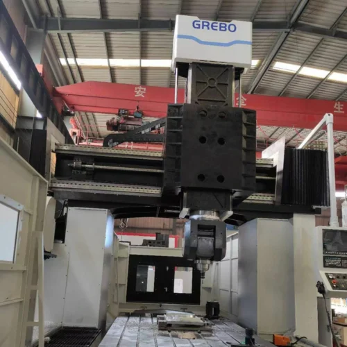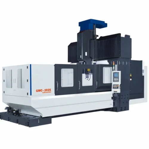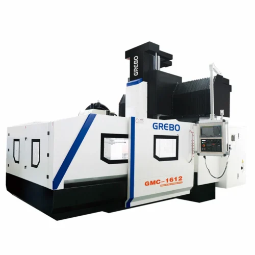

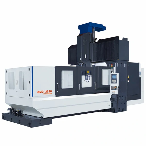
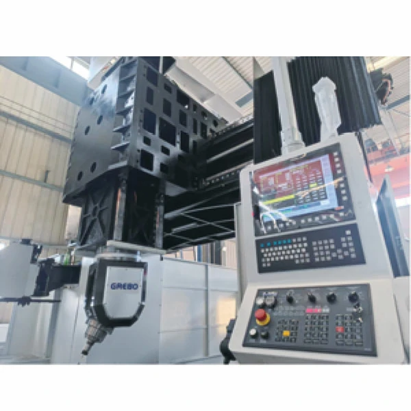
Gantry-style machines replace moving-column mills when a workpiece exceeds single-column reach. The fixed dual-column frame prevents the structural deflection that compromises thin webs and long spars during heavy material removal, delivering first-part accuracy and cutting setup time.
The GMC2520 through GMC4020 cover a 2700mm to 4200mm X-axis range on the same fixed dual-column frame. Model selection in this gantry machining center series depends on workpiece length, not just weight.
Applications
This size class supports milling and boring on large aluminum or titanium aerospace structural components, such as wing spars and fuselage panels. This provides the stability required to machine complex aerospace parts in a single setup. For example, a typical 3.5m wing spar application can be machined end-to-end without intermediate re-fixturing, removing the handling risks associated with multiple setups.
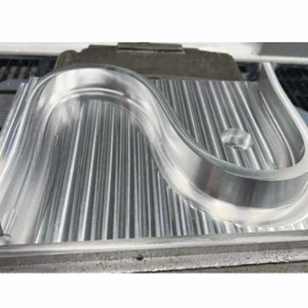
Large injection mold and die-casting mold base plates undergo single-setup, multi-face milling. This keeps the cavity and core sides aligned across a 2.5 to 4 meter span without re-fixturing, which shortens cycle time and maintains cavity-to-core alignment.
Workpieces under 2.5m do not require this frame’s Φ80 leadscrew or table capacity. Smaller options are available in the standard gantry machining center category.
Industries
Aerospace manufacturers machining wing spars and bulkhead frames from aluminum or titanium billet require steady cutting geometry across long, unsupported spans. This configuration maintains wall thickness tolerances on thin-web structures where deflection would otherwise cause scrap.
Mold and die manufacturers producing large injection mold bases and die-casting plates rely on single-setup, multi-face milling. This approach maintains cavity-to-core alignment across 2.5 to 4 meter spans, which is critical for assembly fit.
Heavy Duty Gantry Machining Center Key Features
- A 2000mm column span with 55mm linear guides on the X/Y axes keeps the spindle aligned across the full worktable, limiting lateral drift to maintain consistent surface finish across large parts.
- The X-axis leadscrew steps up from Φ63 on the GMC2520 to Φ80 on larger models, with slide blocks increasing from 8 to 14. Compared with lighter linear-guide-only configurations, this stepped Φ80 screw and increased slide block configuration provides additional support for long-span heavy cutting.
- The Z-axis box way carries the spindle through deep-cavity plunge cuts, providing the rigidity needed to prevent chatter and extend tool life during deep-cavity milling.
- Worktable capacity spans 5 to 9 tons. Projects requiring an even wider bridge fit better on a Large Bridge Type Machining Center.
- Dual screw-type conveyors, a chain conveyor, and a bucket conveyor clear swarf across the 1800mm table. This protects the linear guides, supporting reliable unattended overnight runs.
The leadscrew and slide-block upgrade past the GMC2520 is a mechanical necessity, not a cost increase. X-axis travel beyond 3000mm exerts enough leverage on a Φ63 screw to cause deflection. Heavier hardware maintains the 0.008mm positioning accuracy at full reach.
Why This Gantry Configuration Fits Large Structural Parts
For procurement and engineering teams evaluating large-scale machining, this configuration balances rigidity and footprint:
- Fixed dual-column structure: Eliminates the cantilever effect of moving-column VMCs on wide workpieces.
- 2000mm column spacing: Provides ample clearance for wide mold bases and aerospace spars without compromising spindle support.
- BT50 spindle with box-way Z-axis: Delivers the damping capacity required for heavy roughing, unlike lighter linear-guide-only setups.
- 5 to 9-ton table load: Accommodates massive raw billets and castings without requiring custom sub-frames.
Technical Specifications
The GMC2520 through GMC4020 share a 2000mm column span and BT50 spindle taper. Axis travel, leadscrew diameter, and load capacity scale up across the four models.
| Parameter | Unit | GMC2520 | GMC3020 | GMC3520 | GMC4020 |
|---|---|---|---|---|---|
| X / Y / Z Axis Travel | mm | 2700 / 2000 / 1000 | 3200 / 2000 / 1000 | 3700 / 2000 / 1000 | 4200 / 2000 / 1000 |
| Spindle Nose to Worktable | mm | 180 – 1180 | 180 – 1180 | 180 – 1180 | 180 – 1180 |
| Distance Between Two Columns | mm | 2000 | 2000 | 2000 | 2000 |
| Leadscrew Dia./Pitch (X) | mm | Φ63 / 12 | Φ80 / 20 | Φ80 / 20 | Φ80 / 20 |
| Leadscrew Dia./Pitch (Y/Z) | mm | Φ50 / 10 | Φ50 / 10 | Φ50 / 10 | Φ50 / 10 |
| Guideway Type/Width (X/Y) | mm | 55mm Linear | 55mm Linear | 55mm Linear | 55mm Linear |
| Guideway Type (Z) | – | Box Way | Box Way | Box Way | Box Way |
| Guide Block Qty (X/Y) | pcs | 8 / 4 | 10 / 4 | 10 / 4 | 14 / 4 |
| Worktable Size | mm | 2500 x 1800 | 3000 x 1800 | 3500 x 1800 | 4000 x 1800 |
| T-slot (Qty x Width x Pitch) | mm | 9 x 22 x 190 | 9 x 22 x 190 | 9 x 22 x 190 | 9 x 22 x 190 |
| Max Loading Capacity | Ton | 5 | 6 | 8 | 9 |
| Spindle Taper | – | BT50 | BT50 | BT50 | BT50 |
| Spindle Transmission | – | Belt Drive | Belt Drive | Belt Drive | Belt Drive |
| Spindle Speed | rpm | 6000 | 6000 | 6000 | 6000 |
| Spindle Motor Power (Cont./Peak) | kW | 18.5 / 22 | 18.5 / 22 | 18.5 / 22 | 18.5 / 22 |
| X / Y / Z Fast Moving Speed | m/min | 15 / 15 / 15 | 15 / 15 / 15 | 15 / 15 / 15 | 15 / 15 / 15 |
| Cutting Feed Speed | mm/min | 1 – 8000 | 1 – 8000 | 1 – 8000 | 1 – 8000 |
| Tool Magazine Capacity & Type | pcs | 24, Disc | 24, Disc | 24, Disc | 24, Disc |
| Positioning Accuracy | mm | 0.008 | 0.008 | 0.008 | 0.008 |
| Repeat Accuracy | mm | 0.005 | 0.005 | 0.005 | 0.005 |
| Machine Weight | kg | 21000 | 23500 | 26000 | 28500 |
Typical Application Cases
Typical Application: Large Aerospace Structural Component Machining
Long aluminum or titanium airframe sections, such as wing spars and fuselage panels, are prone to cutting-induced deflection. When only a few support points carry the tool along a multi-meter pass, heat buildup during roughing can shift finished dimensions as the part cools. Machining these parts using the 2000mm column span, 55mm X/Y linear guides, and Z-axis box way keeps the spindle path stable through roughing and finishing without repositioning fixtures.
- Positioning accuracy holds within 0.008mm and repeat accuracy within 0.005mm, as measured per ISO 230-2:2014 across the full working envelope.
- Machining spans up to 4200mm on the GMC4020 in a single setup removes the need for 2 to 3 re-fixturing cycles on a 3.5m spar, which directly cuts repositioning time and preserves dimensional consistency.
- The BT50 taper and 18.5/22kW spindle motor support continuous heavy-alloy roughing without downgrading tooling mid-cycle.
Frequently Asked Questions
What is the maximum workpiece size this gantry machining center can accommodate?
Within this series, X-axis travel reaches 4200mm on the GMC4020. The 2000mm Y-axis and worktable up to 4000 x 1800mm hold up to 9 tons. The maximum capacity depends on the selected model.
How does the gantry structure maintain rigidity across a wide worktable?
The fixed dual-column frame maintains a constant 2000mm span between columns. The 55mm linear guides on the X and Y axes, combined with a Z-axis box way, limit lateral drift and resist spindle deflection across the full table width.
What foundation requirements apply to large gantry machining centers?
Machine weight in this series ranges from 21,000kg to 28,500kg. A reinforced concrete foundation, sized to the specific model’s footprint and load path with proper leveling, is required to maintain long-term positioning accuracy under heavy cutting loads.
When is a gantry machining center preferable to a moving-column VMC?
When a workpiece approaches a width where a moving-column spindle would cantilever off the table end, a fixed dual-column gantry layout holds the spindle centered across the full span. Therefore, this class replaces moving-column VMCs for large panels and mold bases, delivering higher throughput and consistent accuracy by removing mid-process repositioning.
For sizing guidance across the GMC2520-GMC4020 range or a quotation for your specific workpiece envelope, contact our engineering team directly.